

Configuring Software#
Now that the plan for the Homelab is fully outlined, the next steps include the installation of the first two pieces of software required to bootstrap everything else about the lab: Proxmox and the pfSense router.
But before that, it is worth talking about another component that has to be set up, and that is the TP-Link repeater.
TP-Link Repeater#
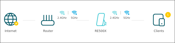
The setup of the TP-Link repeater was rather straightforward. Once it is turned on for the first time, it allows connecting to an open network and starting the initialization. For the setup, I will just repeat the signal of the Wi-Fi network with the same SSID:
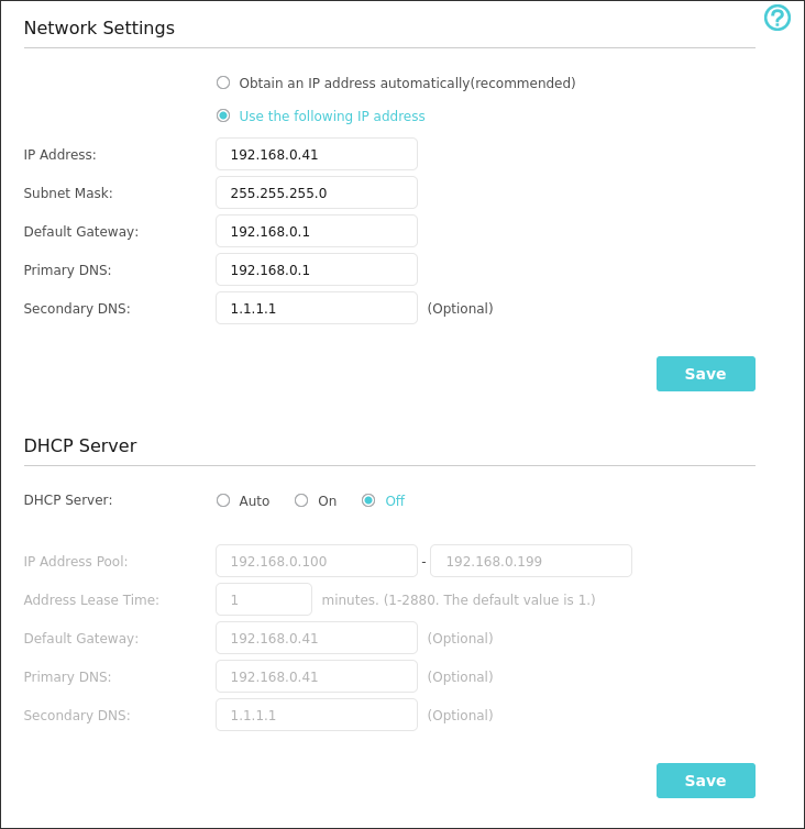
Before closing this part, I tweaked some of the configuration settings to make the setup a bit more stable. These include:
- Setting up a static IP address: this way the repeater is guaranteed to be given the same address every time, in this case
192.168.0.41 - Turning off the DHCP server: to make sure that the ISP router is the only device assigning IP addresses inside the home network, the repeater’s DHCP service is turned off
- Reducing the power of the router’s Wi-Fi signal, since connections only happen via Ethernet
Now that the repeater is set up, the Lenovo laptop (Lancelot) can be connected to it via Ethernet.
Obviously, using the repeater to connect the Lenovo laptop has a cost in terms of speed. The best solution overall to maintain the network speed as much as possible would be to cable the house and link the Lenovo directly to the router.
Proxmox#
Once Lancelot was connected to the repeater, installing Proxmox was straightforward: just download the official ISO, flash it on a drive, and follow the installation instructions.
Miscellaneous#
I went with the default options: I named my main VM node pve and called the bridge network to the home LAN vmbr0. Since I did not purchase a license, I also had to add the no-subscription APT repositories to receive updates.
I also made sure to create a user to allow accessing SSH securely for Terraform operations, as described by the provider’s docs:
# Add a user named 'terraform'
useradd -m terraform

# Install sudo
apt install -y sudo

# Add the possibility to execute the following commands as sudo:
#terraform ALL=(root) NOPASSWD: /usr/sbin/pvesm
#terraform ALL=(root) NOPASSWD: /usr/sbin/qm
#terraform ALL=(root) NOPASSWD: /usr/bin/tee /var/lib/vz/snippets/[a-zA-Z0-9_][a-zA-Z0-9_.-]*
#terraform ALL=(root) NOPASSWD: /usr/bin/sed -i * /etc/pve/lxc/*.conf
#terraform ALL=(root) NOPASSWD: /usr/bin/tee -a /etc/pve/lxc/*.conf
visudo -f /etc/sudoers.d/terraform

# Copy the public ssh key
echo "$PUBLIC_SSH_KEY" > /home/terraform/.ssh/authorized_keysDisks#
Disk-wise, Lancelot has a single SSD with 2.0 TB of space. To start easy, the disk was partitioned to create a single LVM partition containing almost the entirety of the disk space:

The nvme0m1p3 partition is then used to create two storage pools:
local: the pool used to store backups, imports, ISO images, and LXC templates. Total size:100 GBlocal-lvm: the pool used for VM disks. Total size:1.9 TB
Recap graph#
My final Proxmox installation can thus be summarized like this:
flowchart TD
    lancelot["Lancelot
Proxmox node: pve"]
    bridge["vmbr0
Bridge to home LAN"]
    ssd["2 TB NVMe SSD"]
    lvm["LVM partition"]
    local["local
100 GB
ISOs, templates, backups"]
    local_lvm["local-lvm
1.9 TB
VM disks"]

    lancelot --> bridge
    lancelot --> ssd --> lvm
    lvm --> local
    lvm --> local_lvm
pfSense#
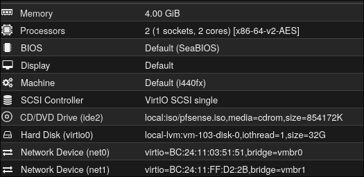
Once Proxmox was set up, I moved on to creating a pfSense virtual machine that would act as my homelab’s internal network router. I will skip explaining details on how I created the VM: it is as simple as downloading the ISO and creating a new VM. The specifics I chose for this machine are:
2vCPU cores4 GBof RAM32 GBof disk space
Virtual Bridges#
Before creating the VM, Proxmox must be aware of the fact that we will be operating on two different networks: the home one and the homelab one. This requires two physical NICs and two separate bridges:
vmbr0: this is the main network bridge that handles traffic towards the home LAN. It covers the subnet192.168.0.0/24. To simplify IP management, the Proxmox host on this interface is given the static IP address of192.168.0.137/24and is able to reach the gateway at192.168.0.1. This address must be outside the ISP router’s DHCP pool or reserved there.vmbr1: this is a VLAN-aware Layer 2 bridge for internal homelab traffic. It is connected to the Ethernet port going to the switch, which is configured as a tagged trunk for VLANs 10 and 20. The bridge has no IP address and does not own a subnet, and pfSense owns the routed VLAN interfaces on top of this trunk.

The pfSense VM can then be created with two separate network devices: the pfSense installation will prompt the user to choose which one handles the WAN (the home network) and the LAN trunk (the homelab network):
Setup#
Once the pfSense installation was completed, it was time to change a couple of components to suit my needs.
Miscellaneous#
For starters, I decided to move the default listening port of pfSense from 443 to 8443: this way port 443 is free to be allocated via NAT to any other internal VM. I also decided to specify a static IP for the WAN interface, 192.168.0.73/24, which is outside the ISP router’s DHCP pool or reserved there.
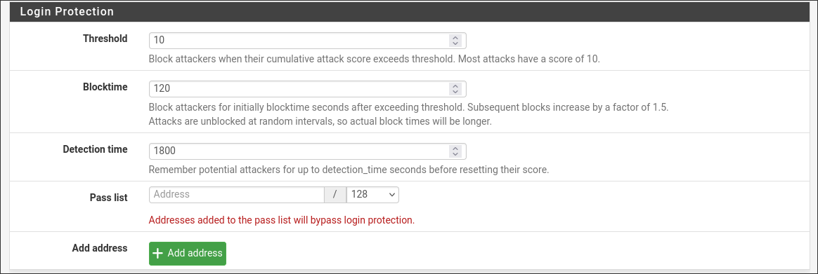
Protection-wise, I enabled SSH access through port 2222, allowing only users with authorized SSH keys and disabling password authentication. I also implemented the default brute-force protections for the login screen:
To harden the account even more, I disabled access from the admin user and created a new one with admin privileges.
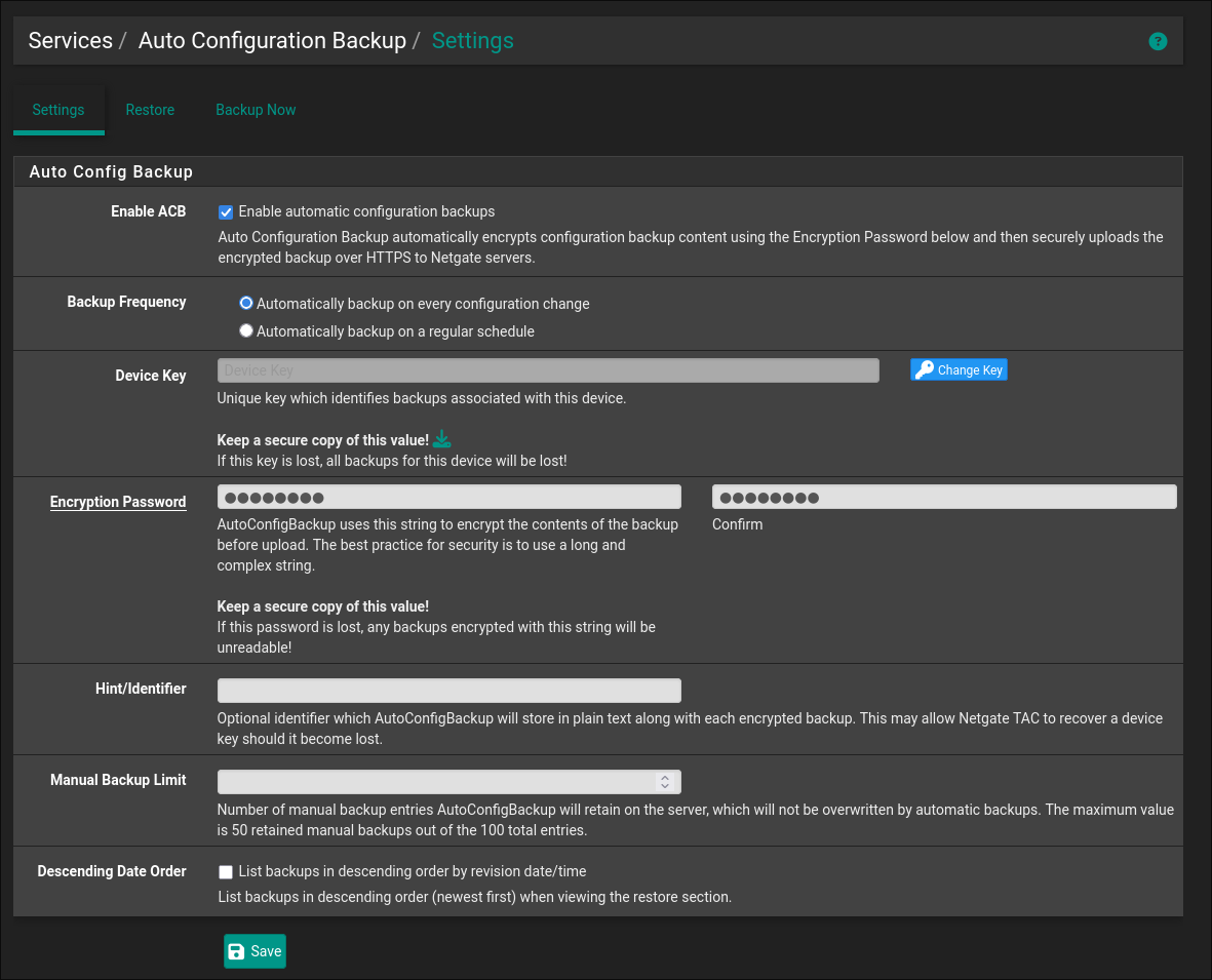
Another very useful option to enable is automatic configuration backup on pfSense servers. By supplying an encryption key, I can keep a version of my configuration and roll back in case anything bad happens.
qemu-user-agentIn order to allow Proxmox to query the status of the pfSense VM, it is necessary to install inside it the qemu-user-agent service. I managed to do this by executing the script contained in this repository: https://github.com/Weehooey/pfSense-scripts
VLANs#
Once pfSense was running, I went to set up the two VLANs that were previously described, 10 and 20:
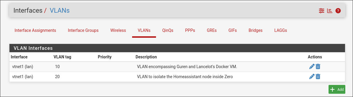
The pfSense LAN vNIC is connected to vmbr1 without a Proxmox VLAN tag, allowing pfSense to receive the VLAN trunk. The physical uplink from vmbr1 to the switch then carries tagged VLANs 10 and 20.
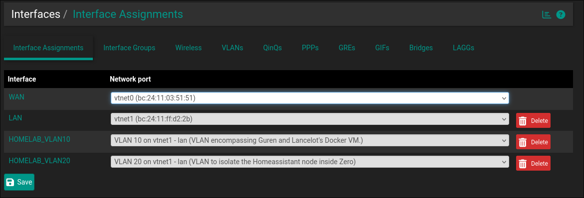
Once the VLANs are created, it is necessary to assign them to two new interfaces, which pfSense uses to route the network segments. I created the interfaces HOMELAB_VLAN10 with the static address 192.168.10.1/24, and HOMELAB_VLAN20 with the static address 192.168.20.1/24. Neither internal interface has an upstream gateway: pfSense is the gateway for its clients.
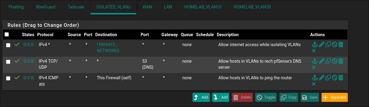
Once the VLAN interfaces are set up, pfSense creates an empty firewall ruleset for each one. By default, the router refuses to route packets arriving from either VLAN, which prevents connectivity to the WAN. Communication to pfSense is also blocked, meaning that hosts inside the VLANs cannot access services such as the DNS resolver on port 53. To avoid this, pfSense docs recommend adding the following rules:
- Traffic towards the router for port
53of both theTCPandUDPprotocol - Traffic towards the router following the
ICMPprotocol - Traffic towards any host that is not part of the following subnets, which are reserved for private networks:
10.0.0.0/8172.16.0.0/12192.168.0.0/16
In pfSense, these ranges are configured in a Network(s) alias, not a Host(s) alias, otherwise pfSense attempts to expand the ranges into individual addresses. The firewall rule uses this alias as its destination with Invert match enabled.
Although this configuration theoretically blocks traffic inside the same VLAN (i.e., 192.168.20.0/24 is a subnet of 192.168.0.0/16) the traffic is actually not blocked, because two devices communicating inside the same network do not reach the pfSense router at all, since communications are handled by the switch (layer 2) and not the router (layer 3). This is explained in greater detail in pfSense’s official docs.
To make rules more manageable (in case more VLANs have to be added in the future), I created an interface group named ISOLATED_VLANS, containing both HOMELAB_VLAN10 and HOMELAB_VLAN20. This way, I could add firewall rules to it and have them apply to each VLAN. The final firewall rules look like this for both interfaces:
Furthermore, I would like to add a third VLAN with id 99, which will be dedicated to management of devices under VLAN 10 and 20. The idea is that devices under this VLAN have their traffic routed by pfSense to devices under 10 and 20, and can receive traffic from the home network. This way, an administrator can use any device connected inside it as an “SSH jump box” to reach the others. The subnet reserved will be 192.168.99.0/24. The firewall configuration looks like this:
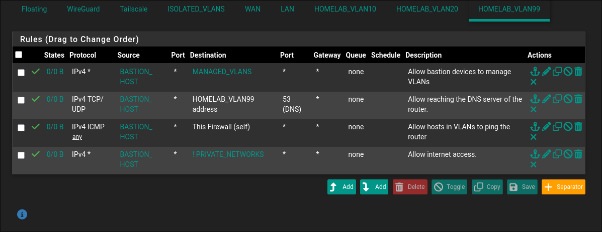
Then, the actual Bastion host (BASTION_HOST alias) will be under 192.168.99.2/24, meaning that to reach from the host network I need to add a NAT rule:
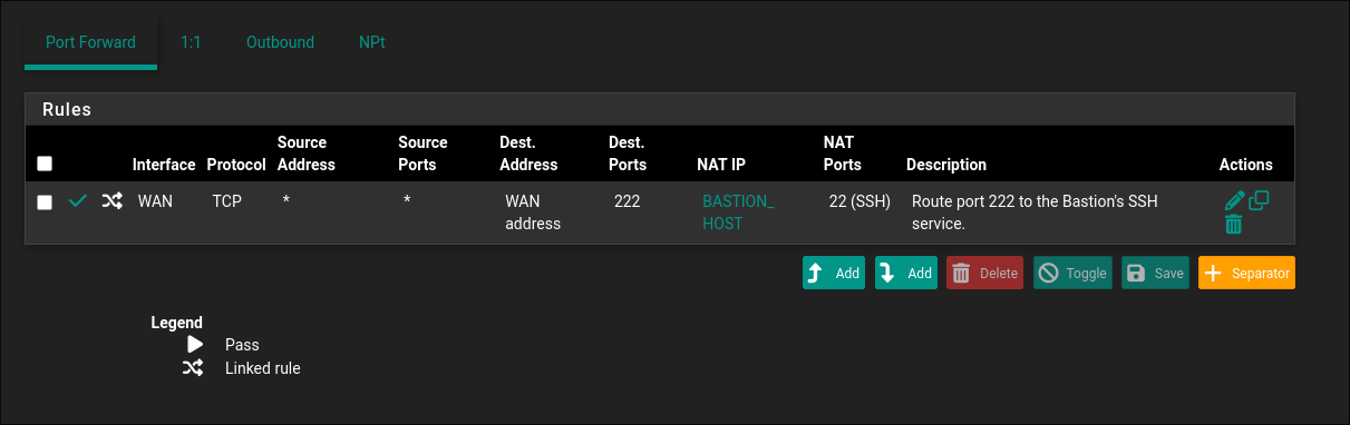
Finally, I had to reserve the static mapping of 192.168.99.2/24 in the DHCP server. However, this can only be done once I actually know the MAC of the Bastion host, which will be configured in the next post.
VPNs#
Since the pfSense panel should not be exposed to the wider internet (for obvious security reasons), the best way to make it reachable from outside the home’s LAN would be to enable connection to it through a VPN. The best choice for this is arguably WireGuard, but I decided to explore another self-hosted alternative, which would be Tailscale with its open-source server, Headscale. The configuration of the Headscale server will be part of a future post because it cannot be run directly from pfSense; it has to be run on the Docker VM inside Proxmox. The only thing that can be done for now is to install the Tailscale package inside pfSense itself and come back to it once Headscale is ready.
DHCP#
The DHCP server must not run on the WAN interface, since it is already managed by the ISP’s router. Instead, DHCP is enabled separately for each internal VLAN interface. A DHCP pool is not a reservation: it is the range from which pfSense dynamically assigns client addresses.
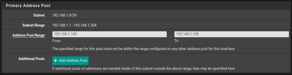
I configured the following DHCP pools:
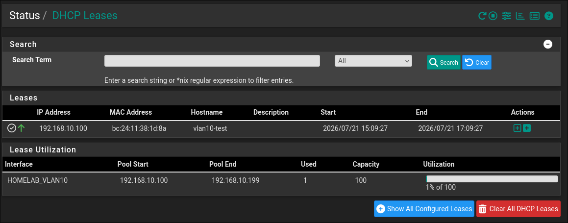
HOMELAB_VLAN10:192.168.10.100-192.168.10.199HOMELAB_VLAN20:192.168.20.100-192.168.20.199
Static mappings are only needed for devices that require a predictable address, such as the Docker VM, the Raspberry Pi 5, and the Raspberry Pi 4. They are configured on the respective VLAN’s DHCP page by mapping a device MAC address to an address outside the dynamic pool, such as 192.168.10.10, 192.168.10.11, and 192.168.20.10.
Switch#
To conclude the network configuration, I had to instruct the TP-Link switch on how to handle traffic for the different VLANs.
General Configurations#
As part of a general series of configurations, I assigned the switch management interface the static address 192.168.10.2/24 on VLAN 10. This address is outside the VLAN 10 DHCP pool and is reachable only from clients permitted to access that VLAN.
VLANs#
Since my switch has a total of 8 ports, the plan was something like this:
- Port
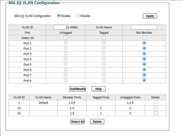
1was dedicated to traffic from the Proxmox host’svmbr1bridge and is marked as carrying both VLANs10and20. This is a trunk port: it carries traffic for multiple VLANs and is therefore VLAN-aware, receiving Ethernet frames with tags that identify their VLAN. The switch uses the VLAN ID and destination MAC address to forward each frame to the appropriate port. - Port
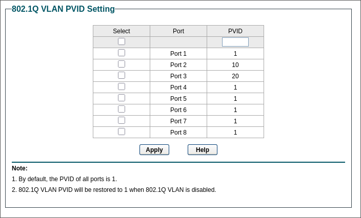
2was dedicated to VLAN10, which contains the Docker VM inside Proxmox and the Pi 5 (Zero). The Docker VM is attached directly tovmbr1with VLAN tag10; the Pi 5 is the device physically connected to this switch port. Since port2is an access port, it carries untagged traffic for VLAN10and has PVID10. The Pi 5 therefore remains VLAN-unaware. - Port
3was dedicated to VLAN20, which contains the Home Assistant Pi (Guren). Like port2, it is an access port that carries untagged traffic for VLAN20and has PVID20. - Ports
4-8become debug ports: by configuring one as an untagged VLAN 10 access port with PVID10, I can attach a laptop and receive an address in192.168.10.0/24. A port can instead be assigned to VLAN 20 when testing that network.
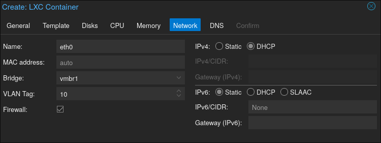
Since the Docker VM is hosted on the same Proxmox instance as pfSense, it must be attached to the VLAN-aware vmbr1 bridge with VLAN tag 10. This keeps it in the same Layer 2 network as the Pi 5 while pfSense remains responsible for routing between VLANs.
The final configuration from the switch’s UI looks like this:
While the PVIDs are these:
Testing#
To verify that the configuration is (at least partially) complete, I tried creating a small LXC container in Proxmox and attached it to VLAN 10:
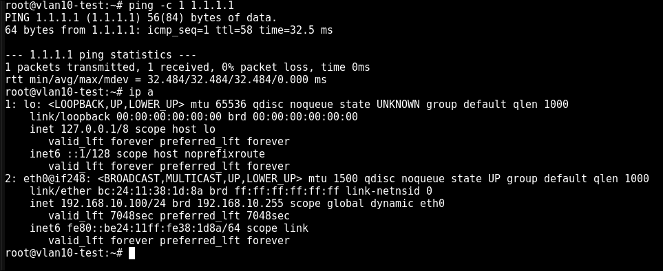
Once the container started I confirmed that network connectivity worked by verifying that the DHCP pool had reserved an address, and WAN connectivity worked successfully:
Wrapping Up#
The configuration should now be complete. In the next posts, I will test it by configuring the various hosts i outlined in previous sections to it. Thanks for following!